Tietosuojalausunto: Yksityisyytesi on meille erittäin tärkeä. Yrityksemme lupaa olla paljastamatta henkilökohtaisia tietojasi mille tahansa laajentumiselle ilman nimenomaista käyttöoikeustasi.
Malli nro.: NSO4GU3AB
kuljetus: Ocean,Air,Express,Land
Maksutapa: L/C,T/T,D/A
Incoterm: FOB,EXW,CIF
4 Gt 1600MHz 240-nastainen DDR3 Udimm
Tarkistushistoria
|
Revision No. |
History |
Draft Date |
Remark |
|
1.0 |
Initial Release |
Apr. 2022 |
|
![]()
Tilaustietotaulukko
|
Model |
Density |
Speed |
Organization |
Component Composition |
|
NS04GU3AB |
4GB |
1600MHz |
512Mx64bit |
DDR3 256Mx8 *16 |
Kuvaus
Hengstar-puskuroimattomat DDR3-SDRAM-dimmit (puskuroimattomat kaksinkertaisen tiedonopeuden synkroniset DRAM-kaksois-linjan muistimoduulit) ovat pienitehoisia, nopean operaation muistimoduuleja, jotka käyttävät DDR3 SDRAM -laitteita. NS04Gu3AB on 512m x 64-bittinen kahden sijoituksen 4 Gt DDR3-1600 CL11 1,5 V SDRAM -palautettu DIMM-tuote, joka perustuu kuusitoista 256m x 8-bittisiä FBGA-komponentteja. SPD on ohjelmoitu JEDEC-standardi latenssi DDR3-1600-ajoitus 11-11-11 1,5 V: llä. Jokainen 240-nastainen DIMM käyttää kultakoskettimia. SDRAM -puskuroimaton DIMM on tarkoitettu käytettäväksi päämuistina asennettuna järjestelmiin, kuten tietokoneisiin ja työasemiin.
ominaisuudet
Voimantoimitus: VDD = 1,5 V (1,425 V - 1,575 V)
VDDQ = 1,5 V (1,425 V - 1,575 V)
800MHz FCK 1600 Mt/s/nasta
8 Itsenäinen sisäinen pankki
Programmoitava CAS -latenssi: 11, 10, 9, 8, 7, 6
Ohjelmoitava lisäaineen latenssi: 0, Cl - 2 tai Cl - 1 -kello
8-bittinen haku
Burst Pituus: 8 (lomitus ilman mitään rajaa, peräkkäin vain aloitusosoitteella “000”), 4 TCCD = 4: llä, joka ei salli saumattomia lukemia tai kirjoita [joko lennossa käyttämällä A12 tai MRS]
Bi-suuntainen differentiaalitieto
Nernal (itse) kalibrointi; Sisäinen itsekalibrointi ZQ -nastalla (RZQ: 240 ohm ± 1%)
Laskujen pääte ODT -nastalla
Merenge -päivitysjakso 7,8US alammassa kuin tcase 85 ° C, 3,9US 85 ° C: ssa <tase <95 ° C
Asynkroninen nollaus
mukauttavaa datanlähetysten voimakkuutta
Fly-by topologia
PCB: Korkeus 1,18 ”(30 mm)
Rohs-yhteensopiva ja halogeenivapaa
Tärkeimmät ajoitusparametrit
|
MT/s |
tRCD(ns) |
tRP(ns) |
tRC(ns) |
CL-tRCD-tRP |
|
DDR3-1600 |
13.125 |
13.125 |
48.125 |
2011/11/11 |
Osoitetaulukko
|
Configuration |
Refresh count |
Row address |
Device bank address |
Device configuration |
Column Address |
Module rank address |
|
4GB |
8K |
32K A[14:0] |
8 BA[2:0] |
2Gb (256 Meg x 8) |
1K A[9:0] |
2 S#[1:0] |
Nastakuvaus
|
Symbol |
Type |
Description |
|
Ax |
Input |
Address inputs: Provide the row address for ACTIVE commands, and the column |
|
BAx |
Input |
Bank address inputs: Define the device bank to which an ACTIVE, READ, WRITE, or |
|
CKx, |
Input |
Clock: Differential clock inputs. All control, command, and address input signals are |
|
CKEx |
Input |
Clock enable: Enables (registered HIGH) and disables (registered LOW) internal circuitry |
|
DMx |
Input |
Data mask (x8 devices only): DM is an input mask signal for write data. Input data is |
|
ODTx |
Input |
On-die termination: Enables (registered HIGH) and disables (registered LOW) |
|
Par_In |
Input |
Parity input: Parity bit for Ax, RAS#, CAS#, and WE#. |
|
RAS#, |
Input |
Command inputs: RAS#, CAS#, and WE# (along with S#) define the command being |
|
RESET# |
Input |
Reset: RESET# is an active LOW asychronous input that is connected to each DRAM and |
|
Sx# |
Input |
Chip select: Enables (registered LOW) and disables (registered HIGH) the command |
|
SAx |
Input |
Serial address inputs: Used to configure the temperature sensor/SPD EEPROM address |
|
SCL |
Input |
Serial |
|
CBx |
I/O |
Check bits: Used for system error detection and correction. |
|
DQx |
I/O |
Data input/output: Bidirectional data bus. |
|
DQSx, |
I/O |
Data strobe: Differential data strobes. Output with read data; edge-aligned with read data; |
|
SDA |
I/O |
Serial |
|
TDQSx, |
Output |
Redundant data strobe (x8 devices only): TDQS is enabled/disabled via the LOAD |
|
Err_Out# |
Output (open |
Parity error output: Parity error found on the command and address bus. |
|
EVENT# |
Output (open |
Temperature event: The EVENT# pin is asserted by the temperature sensor when critical |
|
VDD |
Supply |
Power supply: 1.35V (1.283–1.45V) backward-compatible to 1.5V (1.425–1.575V). The |
|
VDDSPD |
Supply |
Temperature sensor/SPD EEPROM power supply: 3.0–3.6V. |
|
VREFCA |
Supply |
Reference voltage: Control, command, and address VDD/2. |
|
VREFDQ |
Supply |
Reference voltage: DQ, DM VDD/2. |
|
VSS |
Supply |
Ground. |
|
VTT |
Supply |
Termination voltage: Used for control, command, and address VDD/2. |
|
NC |
– |
No connect: These pins are not connected on the module. |
|
NF |
– |
No function: These pins are connected within the module, but provide no functionality. |
HUOMAUTUKSET : Alla oleva PIN -kuvaustaulukko on kattava luettelo kaikista mahdollisista tappeista kaikille DDR3 -moduuleille. Kaikki luetellut nastat toukokuussa ei tueta tässä moduulissa. Katso tämän moduulin erityiset PIN -tehtävät.
Funktionaalinen lohkokaavio
4 Gt, 512MX64 -moduuli (x8: n 2Rank)


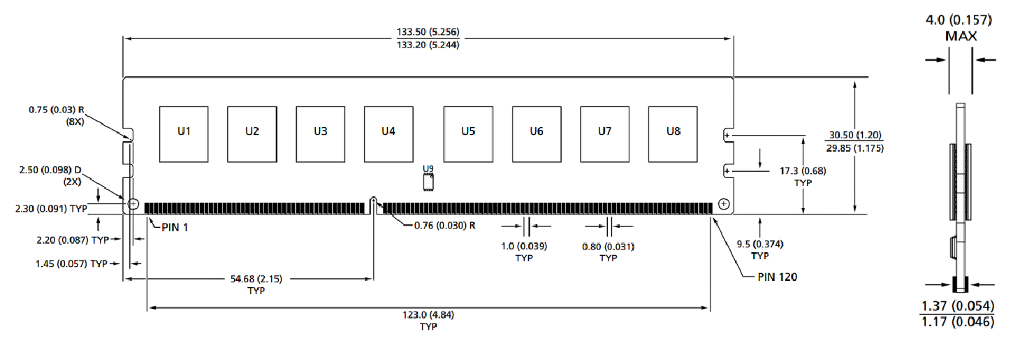
Moduulin mitat
Edestä

Edestä

Huomautuksia:
1. Kaikki mitat ovat millimetreinä (tuumaa); Max/min tai tyypillinen (tyypi), missä merkitty.
2.Toleranssi kaikissa mitoissa ± 0,15 mm, ellei toisin mainita.
3.Mitakaavio on tarkoitettu vain viitteeksi.
Tuoteryhmät : Teollisuus älykäs moduulin lisävarusteet


Tietosuojalausunto: Yksityisyytesi on meille erittäin tärkeä. Yrityksemme lupaa olla paljastamatta henkilökohtaisia tietojasi mille tahansa laajentumiselle ilman nimenomaista käyttöoikeustasi.

Täytä lisätietoja, jotta voit ottaa sinuun yhteyttä nopeammin
Tietosuojalausunto: Yksityisyytesi on meille erittäin tärkeä. Yrityksemme lupaa olla paljastamatta henkilökohtaisia tietojasi mille tahansa laajentumiselle ilman nimenomaista käyttöoikeustasi.